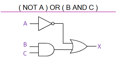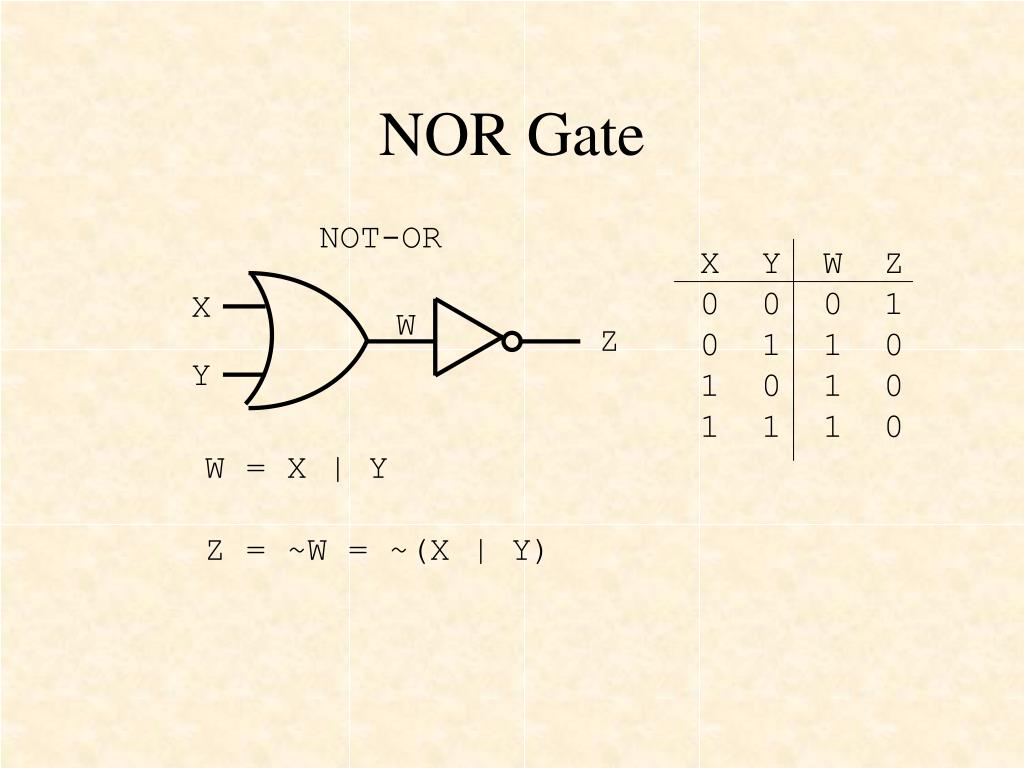
Y (A exor B) = A B = AB’ + A’B Logic diagram and logic equation of XNOR gate The EXOR gate gives a high output every time it detects an inequality in the inputs. XOR gates have two inputs and one output, and they implement the special boolean logic of inequality detection. Y (not A) = A’ = Logic diagram and logic equation of XOR gate NOT gates have one input and one output, and it implements the boolean logic of inversion. Y (A nor B) = Logic diagram and logic equation of NOT gate NOR gates have two inputs and one output, and they implement the inverse boolean logic of addition. It will also show us the implementation of the assignment operator.
#Logic gates equation how to
This program will help us understand how to declare input and output ports in a VHDL program. Since we are using the dataflow modeling architecture to implement all the logic gates, all we need are the logic diagrams and the logic equations of all the gates. This is the first VHDL program in our VHDL course.


Logic diagram and logic equation of XNOR gate.Logic diagram and logic equation of XOR gate.Logic diagram and logic equation of NOT gate.Logic diagram and logic equation of NOR gate.Logic diagram and logic equation of OR gate.Logic diagram and logic equation of NAND gate.Logic diagram and logic equation of AND gate.Explanation of the VHDL code for all logic gates using dataflow method.


 0 kommentar(er)
